Please note: The information supplied here is of a general nature. Some properties have restrictions that are unique to that site. If you have any questions, please call 613-735-6291 for specific information.
What is a porch, verandah, or deck?
Verandahs, porches and decks are all considered as additions to the dwelling. As such they must comply with the required setbacks for the main building, including from the front yard (roads & streets), side yard, and rear yards, and in the country must also be setback a minimum 5 meters from the on-site sewage disposal system.
Important items to note
Please note that the foundation of the proposed structure must be equal to the foundation of the building it is being attached to. If the deck is proposed to be supported by deck blocks, then it cannot be attached to the home. A porch, sunroom or verandah will require a foundation of equal depth as that of the building it is being attached to.
The information contained below is for references only. It is intended to assist homeowners with their deck project while ensuring compliance with the requirements of the Ontario Building Code. The drawings and details specified are typical construction details and other methods may be permitted upon authorization from Building Services at the discretion of the Building Official. Any deviation from this package will require the plans to be sealed by a Professional Engineer or accompany a designer sheet signed for the category of Building Structural. All construction shall be inspected including footings prior to placing concrete, framing and a final inspection prior to use. All construction shall conform to the latest edition of the Building Code, as amended.
| Footings |
|
Shall be constructed in accordance with the requirements below:
- Footings shall bear on solid ground at a minimum of 48” below grade for frost protection.
- Footings shall be deeper if solid ground is not found. Bearing conditions must be verified by the Building Inspector prior to placement of concrete.
- Concrete piers shall extend 6” above grade.
- The size of footings supporting piers and columns shall be based on the tributary load and allowable soil pressure in accordance with Table 1 below.
- The maximum spacing of a pier shall be 10’-0” (3m)
- Minimum 28” x 28” footing is required for pier spacing that exceed 10’-0” (3m)
- Shaded Areas in Table 1 require a Minimum 28” x 28” footing or “Big Foot” Footing System
- Wood framing members that are not pressure-treated with a wood preservative and that are supported on concrete in contact with the ground or fill shall be separated from the concrete by not less than 0.05 mm polyethylene film or Type S roll roofing (not required if 6” above ground).


|
| Deck support posts |
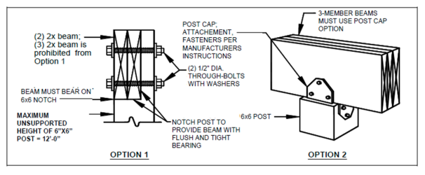
- All deck support posts shall be a minimum 6"x6" with a maximum unsupported height of 10'-0" measured from the top of the footings to the underside of the beam.
- All supports shall be restrained from lateral displacement at the footing. Lateral restraint shall be provided by manufactured connectors or by minimum post embedment of 12 inches in surrounding soils or concrete piers.
- Cut ends of posts shall be field treated with a wood preservative.
Deck beam to deck post connection
- Deck beam to deck post shall be connected together by either a post cap or by a notched post to accommodate all plied of the deck beam and bolted together.
Lateral bracing
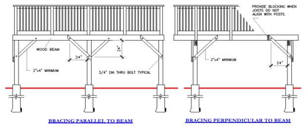
- Lateral bracing of all deck support posts shall be provided for decks that exceed 24" above grade.
|
| Beams |
- Beams are assembled, multi-ply framing members which span between supporting posts. Multi-span decks have more than one beam; spacing between beams is dependent on the allowable span lengths of the supports joist.
- Inside beams have joists bearing from each side. Outside beams have joists, with or without an overhang, bearing from one side.
- Dropped beams have joists bearing above; flush beams have joists with hangers bearing on its sides; multi-span decks are permitted to mix flush and dropped beams.
- Beam size is based on its influence width and longest span length per Table 2. Beam influence width is based on supported joists' span lengths and overhang dimensions.
- Beam span length is measured between the centrelines of two adjacent posts and does not include the beam overhangs.
- Beams may overhang pas the centre of the post up to one-fourth of the actual beam span. For example: 10'-0" x .25 = 2'-6" maximum overhang.
- Flush beams shall have a depth greater than or equal to the deepest joist.

Beam assembly
- The plies of the built-up beam shall be fastened as follows: a) nailed together with a double row of nails not less than 3-1/2” in length, spaced not more than 18” apart in each row with the end nails located 4”-6”from the end of each piece.
b) bolted together with not less than ½” diam. bolts equipped with washers and spaced not more than 48”o.c. with the end bolts located not more than 24” from the ends of the members.
- The distance from the centreline of the fastener to the top or bottom edge of the beam shall be ½-inch minimum.
- The distance from the centreline of the fastener to the ends of the beam shall be 1-inch minimum.
- Beam plies are permitted to have splices. However, splices shall be located at inside posts
|
| Deck joists |
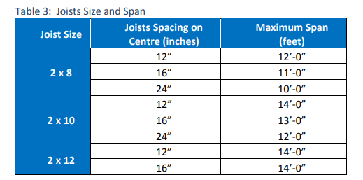
- Joists are repetitively placed framing members spaced at 12, 16, or 24 inches on centre which are supported at each end by a beam or ledger board.
- Single span decks are framed with joists that have one span between supports (not including overhang) as show in Figures 3 and 4. Multi-span decks have joists with more than one span which bear on multiple beams as show in Figures 5 and 6.
- At the house connection, joists bear on the attached ledger board. Joists on a free-standing deck do not connect to the house; instead bearing is provided by an additional beam located at or near the house wall as shown in Figure 7.
Joist spans
- Joist span length is measured from the ledger board to the centreline of the supporting beam or between the centrelines of the supporting beams at each end.
- Joists are permitted to overhang past a beam; joist span length does not include overhangs.
- The joists' design is based on spacing, size, and span length. Note: the overhang dimension shall never exceed one-fourth of the actual joist span. For example: 10'-0" x .25 = 2'-6" maximum overhang.
- Provide full-depth 2x blocking between overhanging joists above beam locations. Exception: blocking may be omitted if the overhang is less than or equal to 2 feet.
- Where blocking between joists is required, attach blocking using joist hangers at each end or by toe-nailing blocking to joists at each end, top and bottom with 10d nails.
- Attach a continuous rim joist or blocking at the joist end as shown in Figures 3, 5, and 7. Attach a rim joist to the end of each joist with (3)10d nails or (3)#10 by 3-inch wood screws.
- When choosing 2x6 joists, the corresponding ledger board must be a 2x8 minimum.
- Guards cannot be attached to decks framed with 2x6 joists.
|
| Stairs |
Stair landing
- Where the total vertical height of a stairway exceeds 12 feet, then an intermediate landing is required and must be constructed as a free-standing deck.
- Stair landings may be constructed with 4x4 posts with heights no greater than 8 feet.
- Landing widths shall be equal to the total width(s) of the stairway(s) served.
Stair stringers
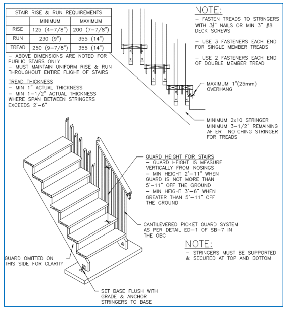
- Stringers shall be of sawn or solid 2x12’s complying with the tread and riser geometry requirements.
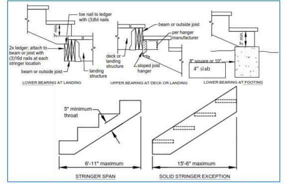
- Stringers shall bear on footings to support a 40# live load or 300# concentrated load over 4 square inches per R301.5, or by the deck or landing they serve. See examples below.
- Stringer span length is measured using the horizontally projected distance between the centerlines of bearing at each end
- The span length of stringer shall not exceed 6 feet-11 inches, and the throat size of cut stringers shall not exceed 5 inches as shown below.
- The span length of a solid stringer with a width equal to 36 inches shall be permitted to have a horizontally projected span up to 15.5 feet when framed solely with two solid stringers. See example below.
|
| Handrails and guards |
- Handrails are required to be installed on every stair with more than 3 risers.
- Provide a guard on both sides of stair where the stair exceeds 6 risers.
- Height of handrails on stairs shall be between 34" (865mm), and 38" (965mm).
- Height of guard for a deck between 24" (600mm) and 5'-11" (1.8m) above grade is 35".
- Height of guard for a deck more than 5'-11" (1.8m) above grade is 42" (1070mm).
- Maximum 4" openings between pickets and no member or attachment between 5.5" (140mm) and 35" (890mm) shall facilitate climbing.
- All steps to be equal rise and run between landings.
Guards
- Minimum height of guards where deck height is between 24” (600mm) & 5’-11” above grade: 35” (890mm)
- Minimum height of guards where deck height exceeds 5’-11” (1.8m) above grade: 42” (1070mm)
- Maximum 4” opening between pickets and no member or attachment between 5-1/2” and 35” shall facilitate climbing · Guard posts shall not be notched. They shall be attached by installing (2) ½” bolts or hold down anchors per manufacturer’s specifications.
- Guardrails must withstand 200 lbs point load in any direction and infill must withstand 50 lbs loading over a one square foot area.
- All fasteners shall be resistant to corrosion. All lumber shall be decay resistant. All cut ends of preservative treated lumber shall be treated to prevent decay.
- Composite decking is required to have BMEC or CCMC approvals
- Pre-engineered guard systems are required to have Ontario Engineering
- Any guard assembly that is site manufactured, such as wood/glass guards is required to be engineered. If a professionally engineered guard is proposed, documentation with an engineer’s stamp may be required.
- A privacy wall/ fence boards is permitted if constructed as a guard and should be discussed with the Building Inspector prior to constructing
|
Apply for a building permit here


.png)


